 RF cat corner
Grounding - planes are a convenience
Nov 06, 2026Grounding is a very important point in modern electronics. The often recommended way to do this is to use a ground plane just below the lines referenced to it. However, the important point is for the ground to follow the signals, and the plane geometry is just a convenience for this. Here is a review of interesting variants.
1. The bunch of coaxial shields
The typical lab bench comprises several metallic boxes connected by coaxial cables. Coaxial cables are used a minima for RF and signals. Serious setups use them also for supplies. In such a setup, the grounding between the boxes is made by the boxes themselves and by the coaxial cables.
1.1 Nuvotronics coax
In the wide scale of the labs, coaxial cables are often used. On the contrary, using modern 3D manufacturing techniques, this techique is also possible on a micro scale. Sure it is very expensive, but definitely working well.
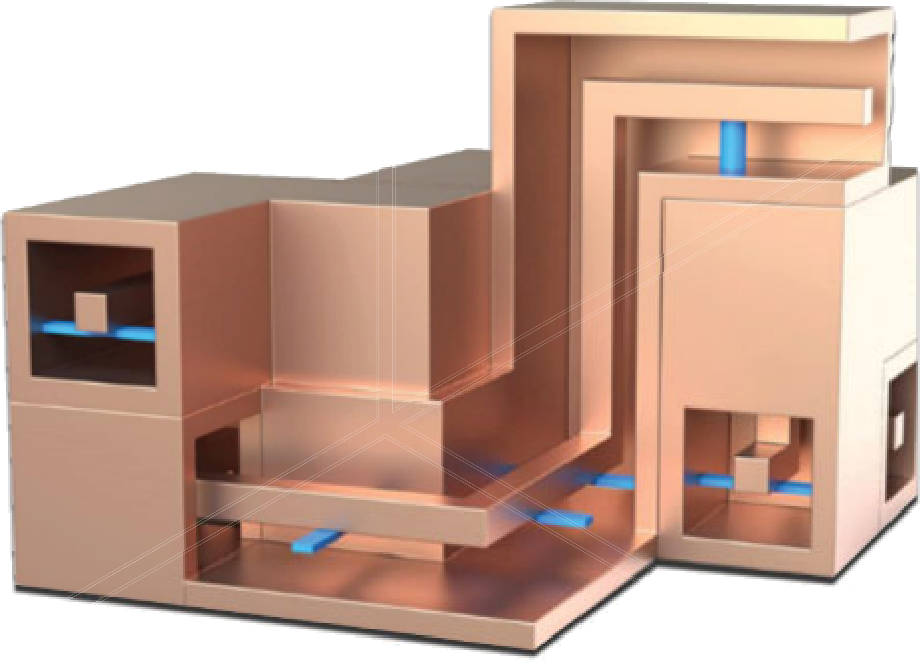 Copyright Cubic Nuvotronics, https://www.cubic.com/sites/default/files/2024-05/2023%20Nuvo%20Product%20brochure_R32_PRINT.pdf
1.2 The bunch of cables with their ground wire
Oh the other hand of the robustness, when connecting various boxes but without shielded cables, accompanying each bunch of connectors by one or several ground wires connected to the grounds on each side is almost always better than the reverse.
This configuration can be seen as a very crude approximation of coaxial lines, however improved when several ground wires are used and tightly coupled to their corresponding signal wires, ideally in a one to one fashion.
2. Differential lines
In the bunch of ground wires approach, I deliberately did not mention the various differential pairs approach, who are probably the very most common approach in consumer electronics: DDR signals, PCIe, Ethernet, USB, and so on.
Roughly speaking, in single-ended lines, you have a big connector, whose potential won’t change a lot precisely because it is big, and a small connector using the big conductor as a potential reference. Let put aside for now questions like the meaning of the potential, how to deal with the multiple definitions of the potential, and to what this potential should be refered to. Just say for now they are important questions for later.
On the contrary, in differential lines, you have a + connector and a - conductor, typically connected to two signal sources with symmetric impedances. Here the question of where is the ground becomes really interesting.
Imagine for whatever reason that instead of a differential line two single-ended lines are used, in a +, GND, GND, - fashion. Since the 2 GND conductors are at the same potential (there are more complicated was to tell this), connecting them don’t change the picture (let aside a few details). Eventually they can be merged into a single unique conductor. But since in this conductor, not current flows (let aside a few details), it can even be removed.
This illustrates that between the conductors of each differential pair there is a surface, behaving like a ground. When the conductors are straight, this surface is a plane, called a symmetry plane, and often modelled in EM simulators as a perfect conducting plane. When the conductors are not straight, for instance in twisted pairs, the shape of this surface is much more convoluted, but you still have a virtual grounding effect.
3. Grids
More often than not, grids are useful for grounding, even if their limitations must be taken into account: they stop working well when the frequency is too high compared to the size of the holes, and it is difficult to have a controlled impedance line with such a ground.
One typical use is shielded boxes with holes for air cooling.
Some decades ago, in 2 layers TTL or CMOS digital boards, a strategy was to route ground and power in grid fashion, and the spacing between the ground lines was used to route signal traces. Note that in this particular case, both ground and supply behave as ground, due to the decoupling capacitors connecting them. Also such circuits did not need controlled impedance lines.
Finally, grids are also convenient for the grounding of a whole room containing shelves of devices.
4. Coplanar
Ground does not need to be below the line. A perfectly working configuration is to have the ground on both sides of the lines. However, is is very important to ensure both grounds are connected together.
A typical very high frequency PCB configuration is to have a mixture between coplan and microstrip called grounded coplanar microstrip where grounds are both on the sides and below, regularly connected through vias.
On PCBs, the typical dimensions lead to a microstrip dominant operation, and the side grounds mainly improve shielding. However, on some MMICs, the dimensions lead to a coplanar dominant operation.
5. Weirder shapes
In more complex case, the ground can have a non regular shape, either to achieve a particular effect, or just a convenience.
A first example is this schme I used a few years before to achieve the impedances I wanted while keeping the trace widths I wanted. The ground plane with the ground and the metalic part on which it is attached behave as a single ground conductor.

A second example are hybrid modules. Here, inputs and outputs have coaxial shapes, ground is all around all sections of the circuits, and a ground plane is provided everywhere.
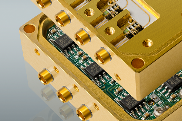 Copyright SemiGen, https://www.semigen.net/about/
Conclusion
While planes are very convenient, they are only a convenience. The key point is to have for each signal line a return conductor tightly coupled to it.