 RF cat corner
IQ modulator and quadrature coupler sign issues.
05 Nov 2024Update from 2024-11-05: Steve from Microwaves 101 also tackled this topic (https://www.microwaves101.com/encyclopedias/branchline-coupler-port-definition), proposing a different port-naming convention for the branchline coupler. Steve names the direct and coupled outputs in reverse compared to the approach I use. His convention offers some interesting arguments: the output he names "forward" exhibits a higher bandwidth and flatter phase response.
Upon further analysis, it appears that the operating principles of branchline couplers differ significantly from those of coupled line couplers. Consequently, the terms "direct" and "coupled," commonly used for coupled line couplers, no longer carry the same meaning.
For now, I’ll retain the "geometric" convention I initially used, as it seems more common, although I’m not entirely convinced it’s more "correct." Examples that follow this convention can be found in this research, this diagram, this article, and this paper).
Many thanks to Steve for raising this interesting topic. Thanks also ChatGPT for improving my English.
Introduction
IQ modulators and quadrature couplers are often used together to perform a frequency translation while rejecting the unwanted sideband. However, the documentation often does not clarify whether the quadrature signal has a +90° or -90° phase shift, and whether the IQ modulator expects a quadrature input with a +90° or -90° phase shift.
The purpose of this page is to clarify this sign issue.
Upconverter side
Here, we assume an upconverter is used. The principle of an IQ upconverter is to perform a complex frequency translation as follows:
In the case of a complex cosine signal in baseband with frequency &&\omega_b&&:
By application of the trigonometric identity &&sin(x) = cos(x - pi / 2)&&:
This clearly shows that the Q input has a phase lag compared to the I input, which is a -90° phase.
Coupler side case 1: coupled line coupler
Let’s assume that the coupled line coupler QCH-451+ from Mini-Circuits is used. The datasheet indicates which port is the quadrature output but not whether its phase is +90° or -90°.
Using ChatGPT and Plotly, the following plots were easily generated:
It’s clear from the plots than the quadrature output has a +90° phase (lead) compared to the in-phase output.
Besides clarifying the +/-90° sign issue, it is useful to check to what physical element correspond each port number. The hypothesis is that this coupler is made with an equivalent to coupled lines performed using an LC network, as pure coupled lines are obviously too long to fit in the component.
Analysis of the transmission curves enables to deduce the connexions:
-
At low frequencies, total transmission from port 1 to port 3 and no transmission to the other ports. Thus both ports are connected to the same first transmission line and ports 2 and 3 are connected to the second line.
-
Port 4 is not connected at low frequencies but is coupled in the band. So port 4 is the coupled port of the other line.
-
Port 2 is not connecter at low frequencies and remains approximately isolated in the band. So port 2 is the coupled output of the second line.
This leads to the following schematic, compared to the datasheet information:

|

|
The symmetry of the schematic is coherent with the symmetry of the table given in the Mini-Circuits datasheet:

The +90 phase shift stays even at low frequencies. This is coherent with the similar behaviour of an high-pass CR network, which is part of the equivalent schematic at low frequencies.
Coupler side case 2: branch-line coupler
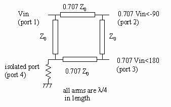
In this part, the ports are numbered like in Microwaves101 (https://www.microwaves101.com/encyclopedias/branchline-couplers), from which this schematic is taken:
This part was performed in two steps. First, using scikit-rf with a some help of ChatGPT, a Python script was created to produce preliminary plots and an s4p file. The second step was to reuse the plotting code from the previous section, with some help from ChatGPT to refactor the duplicate parts, to make the following plots:
Contrary to coupled lines, which have a very broadband quadrature effect, the branch-line coupler has a narrowband quadrature effect. This is still useful for narrowband applications.
It’s clear from the plots than the coupled output has a -90° phase (lag) compared to the direct output.
Conclusion
Quadrature couplers are important for making image reject mixers, but the actual phase sign is sometimes not clearly stated. According to the theory, IQ mixers needs a -90° phase (lag) for the Q input. For coupled lines couplers, the coupled output has a +90° (lead) phase compared to the uncoupled output. Conversely, for branchline couplers, the coupled output has a -90° (lag) phase compared to the uncoupled output. These points must be considered when selecting the wanted mixer side.