 RF cat corner
MLCC voltage dependence.
24 Apr 2024This content was originally published on Microwaves 101 (https://www.microwaves101.com/encyclopedias/capacitor-voltage-effects). Many thanks to Steve for improvements on the original version. Have a look on his website for more interesting content.
This page was suggested by Hadrien, who has had recent experience in MLC capacitor variations with voltage. Did you know your capacitor nominal value can drop 80% when you apply a DC voltage to it? Worse, there does not seem to be any standards for voltage variations like there are for temperature variations.
This page is primarily discussing MLCCs, or multi-layer cerami capacitors, in Class 2. Class 2 uses exotic dielectrics such as barium titanate (BaTiO) with some other strange additives in order to get high dielectric constant in the thousande (to increase capaitance density). Barium titanate is a ferro-electric material, which is the source of voltage/capacitance misery.
From here down, thanks to Hadrien!
Case study
Since this page was originally written for Microwaves101, the case study to illustrate this problem was taken from it. Suppose we want to redesign the good old breadboard RF pulsed (https://www.microwaves101.com/encyclopedias/breadboard-rf-modulator) source from 2006 with more recent components (first version of this page written in 2019). Start by the capacitors. Capacitors values which were at this time most often made with electrolytic capacitors are nowadays more often made with MLCC (multiple layers caramic) capacitors.
To replace the 4.7 µF capacitor, a simple search gives this component:
https://fr.rs-online.com/web/p/condensateurs-ceramique-multicouche/8467296/ (4.7 µF)
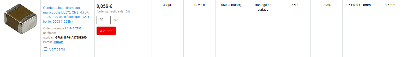
Seems rather nice, and smaller than the original. Wrong! Let’s check the detailed characteristics:
https://www.murata.com/en-global/products/productdetail.aspx?partno=GRM188R61A475KE15%23
Not good! If we need the 4.7 µF capacitance value, we’ll be soon in trouble.
Let’s search a bigger capacitor. We search the biggest value among MLCC capacitors having 10 V rating. https://fr.rs-online.com/web/c/passifs/condensateurs/condensateurs-ceramique-multicouche/?applied-dimensions=4294244793,4291386526&pn=1 We find some nice models:
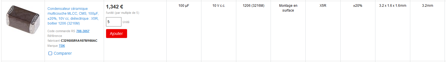
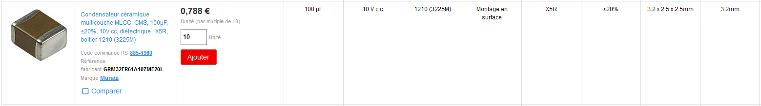
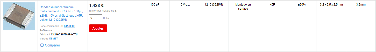
Let’s plot together their bias characteristics1,2,3,4,5,6:
The values of the capacitors at 5 V range from 28.7 to 45.9 µF. Still low for 100 µF capacitors but all would be more than sufficient to replace the 4.7 µF capacitor of the original design.
Personnally, to keep some safety margin from the maximum voltage, I don’t like using a capacitor at a voltage where its capacitance drops more than 50 % of its nominal value. So, if I had to redesign this board, I would continue searching capacitors, even when the Murata and Kemet capacitors are close matches.
Conclusion of case study
As a conclusion, the “100 µF” capacitors of our study, when a DC voltage is applied to them, have an actual capacitance value much lower than their nominal value. This capacitance value would be still sufficient for our application because we oversized the capacitor. However, to keep a sufficient margin from voltage breakdown, I find careful to not use a capacitor at a voltage where its capacitance drop is more than 50 %. In designs where the capacitors are undersized, the capacitance drop effect on applied voltage can be a bad surprise and lead to severe troubles. Such problems are pretty hard to debug if not aware because the cap meters instruments most often measure at 0 V.
An other interesting point is what happens when we combine both biasing and temperature effects. Let’s see an other curve provided by TDK:
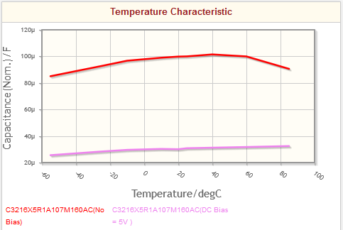
The temperature dependence is better when biased. This leads to the conclusion that temperature coefficient is most often less troublesome than voltage coefficient for MLCC capacitors.
-
https://fr.rs-online.com/web/p/condensateurs-ceramique-multicouches/8851960/ ↩
-
https://www.murata.com/en-global/products/productdetail.aspx?partno=GRM32ER61A107ME20%23 ↩
-
https://fr.rs-online.com/web/p/condensateurs-ceramique-multicouches/1084055 ↩
-
https://product.tdk.com/en/search/capacitor/ceramic/mlcc/info?part_no=C3216X5R1A107M160AC ↩
-
https://fr.rs-online.com/web/p/condensateurs-ceramique-multicouches/8410809/ ↩