 RF cat corner
RC phase shift oscillator draft
29 Mar 2026RC phase shift oscillator
Less popular than the Wien bridge oscillator, the RC phase shift oscillator works by using a chain of 3 high-pass RC networks having a -180° phase shift at the oscillation frequency followed by an inverser amplifier having a 180° phase shift circuit.
It must be emphasized that at least 2 variants of this circuit exists with differences in their operation, particularly in how the phase shift is split between sections.
The schematic and the output waveform are shown below:
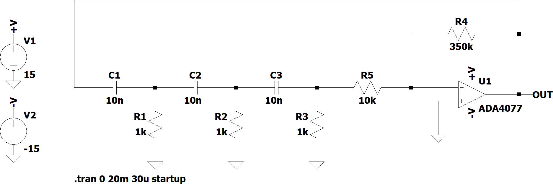

The analysis of this circuit is complex. The attenuation and phase shift of the different sections is not the same since each RC section is loaded by a different impedance: C3+R5 behave as an (almost) unloaded RC network, C2+R2 are loaded by C3+R5, C1+R1 are loaded by the chain starting with C2+R2.
R5 is chosen big enough to not load C3+R3. It is tempting to use its value alone instead of R3, because the input resistance of this inverting amplifier when feedback is active is equal to the first resistance R5. However, when clipping occurs, this is not exactly the case anymore.
The advance of phase between Vout and the successive RC stages can be clearly seen in the figure. The strange transient on the output of the last RC filter is actually normal. It is due to the clipping of the waveform after several high pass filterings. For this reason, it is not present during the startup of the oscillator shown below:

Despite the complex analysis, provided that all RC sections use the sames R and C values, simpler formulas are available. See https://en.wikipedia.org/wiki/Phase-shift_oscillator.